Geometry
Overview
The geometry package provides classes useful for many physical simulations in Euclidean spaces, like vectors and rotations in 3D, as well as on the sphere. It also provides a general implementation of Binary Space Partitioning Trees (BSP trees).
All supported type of spaces (Euclidean 3D, Euclidean 2D, Euclidean 1D, 2-Sphere and 1-Sphere) provide dedicated classes that represent complex regions of the space as shown in the following table:
| Regions | |
|---|---|
| Space | Region |
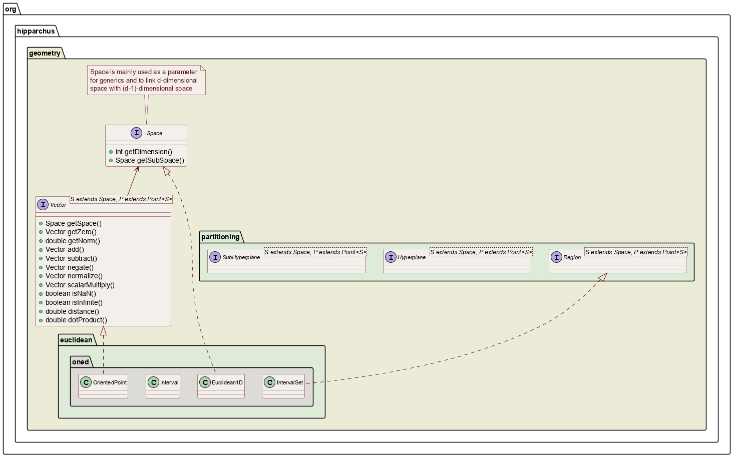
| Euclidean 1D | IntervalsSet |
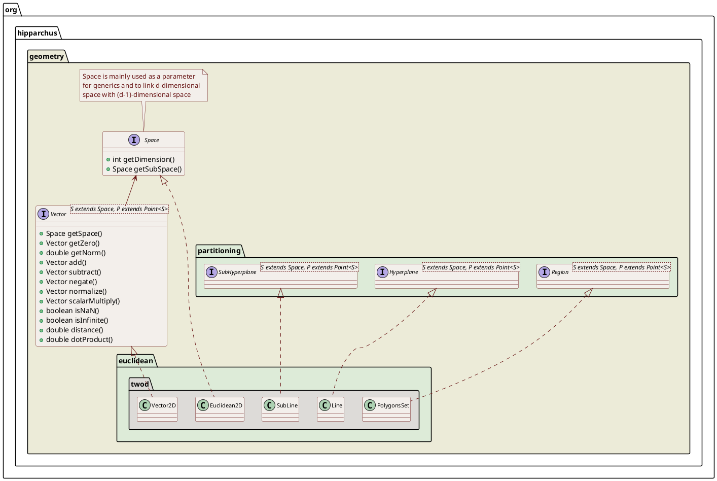
| Euclidean 2D | PolygonsSet |
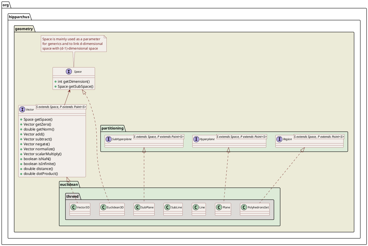
| Euclidean 3D | PolyhedronsSet |
| 1-Sphere | ArcsSet |
| 2-Sphere | SphericalPolygonsSet |
All these regions share common features. Regions can be defined from several non-connected parts. As an example, one PolygonsSet instance in Euclidean 2D (i.e. the plane) can represent a region composed of several separated polygons separate from each other. They also support regions containing holes. As an example a SphericalPolygonsSet on the 2-Sphere can represent a land mass on the Earth with an interior sea, where points on this sea would not be considered to belong to the land mass. Of course more complex models can also be represented and it is possible to define for example one region composed of several continents, with interior sea containing separate islands, some of which having lakes, which may have smaller island … In the infinite Euclidean spaces, regions can have infinite parts. for example in 1D (i.e. along a line), one can define an interval starting at abscissa 3 and extending up to infinity. This is also possible in 2D and 3D. For all spaces, regions without any boundaries are also possible so one can define the whole space or the empty region.
The classical set operations are available in all cases: union, intersection, symmetric difference (exclusive or), difference, complement. There are also region predicates (point inside/outside/on boundary, emptiness, other region contained). Some geometric properties like size, or boundary size can be computed, as well as barycenters on the Euclidean space. Another important feature available for all these regions is the projection of a point to the closest region boundary (if there is a boundary). The projection provides both the projected point and the signed distance between the point and its projection, with the convention distance to boundary is considered negative if the point is inside the region, positive if the point is outside the region and of course 0 if the point is already on the boundary. This feature can be used for example as the value of a function in a root solver to determine when a moving point crosses the region boundary.
Euclidean spaces
Vector1D , Vector2D and Vector3D provide simple vector types. One important feature is that instances of these classes are guaranteed to be immutable, this greatly simplifies modeling dynamical systems with changing states: once a vector has been computed, a reference to it is known to preserve its state as long as the reference itself is preserved.
Numerous constructors are available to create vectors. In addition to the straightforward Cartesian coordinates constructor, a constructor using azimuthal coordinates can build normalized vectors and linear constructors from one, two, three or four base vectors are also available. Constants have been defined for the most commons vectors (plus and minus canonical axes, null vector, and special vectors with infinite or NaN coordinates).
The generic vectorial space operations are available including dot product, normalization, orthogonal vector finding and angular separation computation which have a specific meaning in 3D. The 3D geometry specific cross product is of course also implemented.
Vector1DFormat , Vector2DFormat and Vector3DFormat are specialized classes for formatting output or parsing input with text representation of vectors.
Rotation represents 3D rotations. Rotation instances are also immutable objects, as Vector3D instances.
Rotations can be represented by several different mathematical entities (matrices, axe and angle, Cardan or Euler angles, quaternions). This class presents a higher level abstraction, more user-oriented and hiding implementation details. Well, for the curious, we use quaternions for the internal representation. The user can build a rotation from any of these representations, and any of these representations can be retrieved from a Rotation instance (see the various constructors and getters). In addition, a rotation can also be built implicitly from a set of vectors and their image.
This implies that this class can be used to convert from one representation to another one. For example, converting a rotation matrix into a set of Cardan angles can be done using the following single line of code:
double[] angles = new Rotation(matrix, 1.0e-10).getAngles(RotationOrder.XYZ, RotationConvention.FRAME_TRANSFORM); Focus is oriented on what a rotation does rather than on its underlying representation. Once it has been built, and regardless of its internal representation, a rotation is an operator which basically transforms three dimensional vectors into other three dimensional vectors. Depending on the application, the meaning of these vectors may vary as well as the semantics of the rotation.
For example in a spacecraft attitude simulation tool, users will often consider the vectors are fixed (say the Earth direction for example) and the rotation transforms the coordinates coordinates of this vector in inertial frame into the coordinates of the same vector in satellite frame. In this case, the rotation implicitly defines the relation between the two frames (we have fixed vectors and moving frame). Another example could be a telescope control application, where the rotation would transform the sighting direction at rest into the desired observing direction when the telescope is pointed towards an object of interest. In this case the rotation transforms the direction at rest in a topocentric frame into the sighting direction in the same topocentric frame (we have moving vectors in fixed frame). In many case, both approaches will be combined, in our telescope example, we will probably also need to transform the observing direction in the topocentric frame into the observing direction in inertial frame taking into account the observatory location and the Earth rotation.
In order to support naturally both views, the enumerate RotationConvention has been introduced in version 3.6. This enumerate can take two values: VECTOR_OPERATOR or FRAME_TRANSFORM. This enumerate must be passed as an argument to the few methods that depend on an interpretation of the semantics of the angle/axis. The value VECTOR_OPERATOR corresponds to rotations that are considered to move vectors within a fixed frame. The value FRAME_TRANSFORM corresponds to rotations that are considered to represent frame rotations, so fixed vectors coordinates change as their reference frame changes.
These examples show that a rotation means what the user wants it to mean, so this class does not push the user towards one specific definition and hence does not provide methods like projectVectorIntoDestinationFrame or computeTransformedDirection. It provides simpler and more generic methods: applyTo(Vector3D) and applyInverseTo(Vector3D).
Since a rotation is basically a vectorial operator, several rotations can be composed together and the composite operation r = r<sub>1</sub> o r<sub>2</sub> (which means that for each vector u, r(u) = r<sub>1</sub>(r<sub>2</sub>(u))) is also a rotation. Hence we can consider that in addition to vectors, a rotation can be applied to other rotations as well (or to itself). With our previous notations, we would say we can apply r<sub>1</sub> to r<sub>2</sub> and the result we get is r = r<sub>1</sub> o r<sub>2</sub>. For this purpose, the class provides the methods: compose(Rotation, RotationConvention) and composeInverse(Rotation, RotationConvention). There are also shortcuts applyTo(Rotation) which is equivalent to compose(Rotation, RotationConvention.VECTOR_OPERATOR) and applyInverseTo(Rotation) which is equivalent to composeInverse(Rotation, RotationConvention.VECTOR_OPERATOR).
n-Sphere
The Hipparchus library provides a few classes dealing with geometry on the 1-sphere (i.e. the one dimensional circle corresponding to the boundary of a two-dimensional disc) and the 2-sphere (i.e. the two dimensional sphere surface corresponding to the boundary of a three-dimensional ball). The main classes in this package correspond to the region explained above, i.e. ArcsSet and SphericalPolygonsSet.
Binary Space Partitioning
BSP trees are an efficient way to represent space partitions and to associate attributes with each cell. Each node in a BSP tree represents a convex region which is partitioned in two convex sub-regions at each side of a cut hyperplane. The root tree contains the complete space.
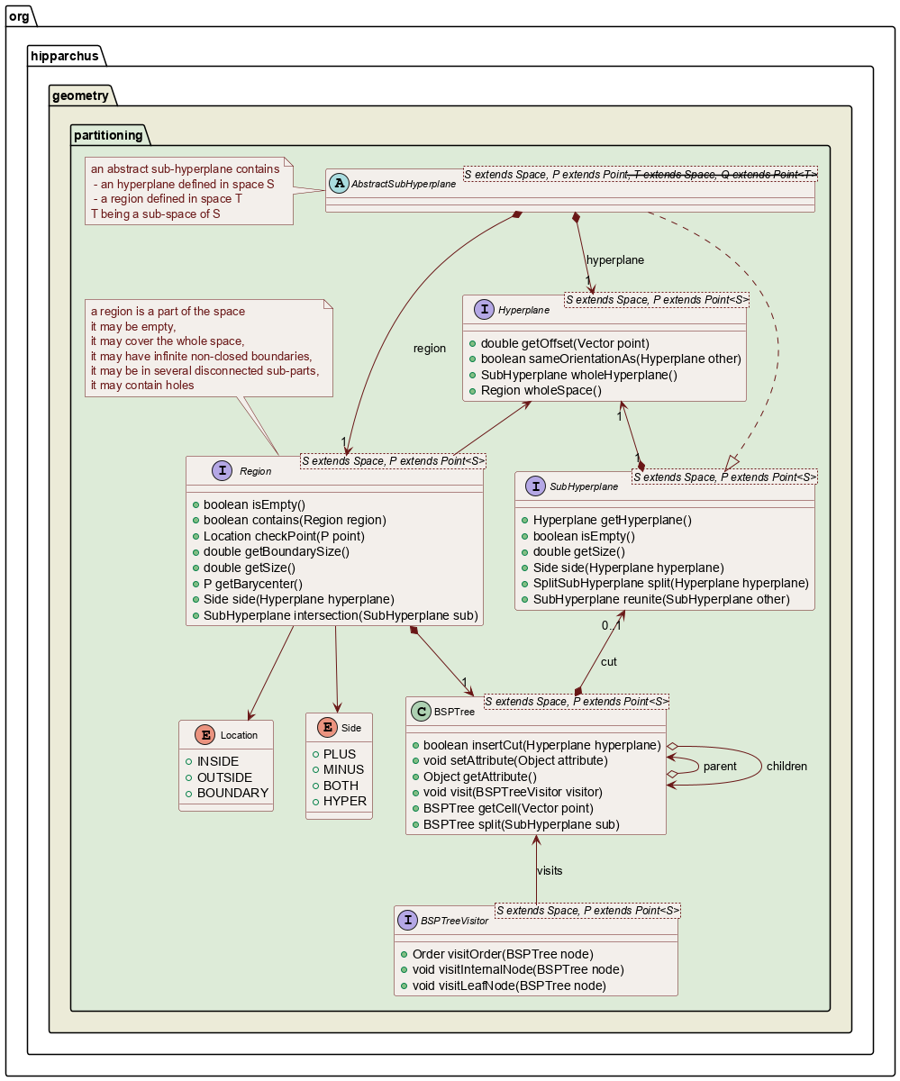
The main use of such partitions is to use a boolean attribute to define an inside/outside property, hence representing arbitrary polytopes (line segments in 1D, polygons in 2D and polyhedrons in 3D) and to operate on them. This is how the regions explained above in the Euclidean and Sphere spaces are implemented. The partitioning package provides the engine to do the computation, but not the dimension-specific implementations. The various interfaces in this package (hyperplane, sub-hyperplane, embedding, and even region) are therefore not considered to be reusable public interface, they are private interface. They may change and users are not expected to rely directly on them. What users can rely on is the BSP tree class itself, and the space-specific implementations of the interfaces (i.e. Plane in 3D as the implementation of hyperplane, or S2Point on the 2-Sphere as the implementation of Point).
Another example of BST tree use would be to represent Voronoi tesselations, the attribute of each cell holding the defining point of the cell. This is not available yet.
The application-defined attributes are shared among copied instances and propagated to split parts. These attributes are not used by the BSP-tree algorithms themselves, so the application can use them for any purpose. Since the tree visiting method holds internal and leaf nodes differently, it is possible to use different classes for internal nodes attributes and leaf nodes attributes. This should be used with care, though, because if the tree is modified in any way after attributes have been set, some internal nodes may become leaf nodes and some leaf nodes may become internal nodes.
Regions
The regions in all Euclidean and spherical spaces are based on BSP-tree using a Boolean attribute in the leaf cells representing the inside status of the corresponding cell (true for inside cells, false for outside cells). They all need a tolerance setting that is either provided at construction when the region is built from scratch or inherited from the input regions when a region is build by set operations applied to other regions. This setting is used when the region itself will be used later in another set operation or when points are tested against the region to compute inside/outside/on boundary status. This tolerance is the thickness of the hyperplane. Points closer than this value to a boundary hyperplane will be considered on boundary. There are no default values anymore for this setting (there was one when BSP-tree support was introduced, but it created more problems than it solved, so it has been intentionally removed). Setting this tolerance really depends on the expected values for the various coordinates. If for example the region is used to model a geological structure with a scale of a few thousand meters, the expected coordinates order of magnitude will be about 103 and the tolerance could be set to 10-7 (i.e. 0.1 micrometer) or above. If very thin triangles or nearly parallel lines occur, it may be safer to use a larger value like 10-3 for example. Of course if the BSP-tree is used to model a crystal at atomic level with coordinates of the order of magnitude about 10-9 the tolerance should be drastically reduced (perhaps down to 10-20 or so).
The recommended way to build regions is to start from basic shapes built from their boundary representation and to use the set operations to combine these basic shapes into more complex shapes. The basic shapes that can be constructed from boundary representations must have a closed boundary and be in one part without holes. Regions in several non-connected parts or with holes must be built by building the parts beforehand and combining them. All regions (IntervalsSet, PolygonsSet, PolyhedronsSet, ArcsSet, SphericalPolygonsSet) provide a dedicated constructor using only the mandatory tolerance distance without any other parameters that always create the region covering the full space. The empty region case, can be built by building first the full space region and applying the RegionFactory.getComplement() method to it to get the corresponding empty region, it can also be built directly for a one-cell BSP-tree as explained below.
Another way to build regions is to create directly the underlying BSP-tree. All regions (IntervalsSet, PolygonsSet, PolyhedronsSet, ArcsSet, SphericalPolygonsSet) provide a dedicated constructor that accepts a BSP-tree and a tolerance. This way to build regions should be reserved to dimple cases like the full space, the empty space of regions with only one or two cut hyperplances. It is not recommended in the general case and is considered expert use. The leaf nodes of the BSP-tree must have a Boolean attribute representing the inside status of the corresponding cell (true for inside cells, false for outside cells). In order to avoid building too many small objects, it is recommended to use the predefined constants Boolean.TRUE and Boolean.FALSE. Using this method, one way to build directly an empty region without complementing the full region is as follows (note the tolerance parameter which must be present even for the empty region):
PolygonsSet empty = new PolygonsSet(new BSPTree<Euclidean2D>(false), tolerance);
In the Euclidean 3D case, the PolyhedronsSet class has another specific constructor to build regions from vertices and facets. The signature of this constructor is:
PolyhedronsSet(List<Vector3D> vertices, List<int[]> facets, double tolerance);
The vertices list contains all the vertices of the polyhedrons, the facets list defines the facets, as an indirection in the vertices list. Each facet is a short integer array and each element in a facet array is the index of one vertex in the list. So in our cube example, the vertices list would contain 8 points corresponding to the cube vertices, the facets list would contain 6 facets (the sides of the cube) and each facet would contain 4 integers corresponding to the indices of the 4 vertices defining one side. Of course, each vertex would be referenced once in three different facets.
Beware that despite some basic consistency checks are performed in the constructor, not everything is checked, so it remains under caller responsibility to ensure the vertices and facets are consistent and properly define a polyhedrons set. One particular trick is that when defining a facet, the vertices must be provided as walking the polygons boundary in trigonometric order (i.e. counterclockwise) as seen from the external side of the facet. The reason for this is that the walking order does define the orientation of the inside and outside parts, so walking the boundary on the wrong order would reverse the facet and the polyhedrons would not be the one you intended to define. Coming back to our cube example, a logical orientation of the facets would define the polyhedrons as the finite volume within the cube to be the inside and the infinite space surrounding the cube as the outside, but reversing all facets would also define a perfectly well behaved polyhedrons which would have the infinite space surrounding the cube as its inside and the finite volume within the cube as its outside!
If one wants to further look at how it works, there is a test parser for PLY file formats in the unit tests section of the library and some basic ply files for a simple geometric shape (the N pentomino) in the test resources. This parser uses the constructor defined above as the PLY file format uses vertices and facets to represent 3D shapes.